Description
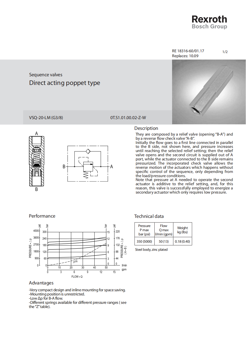
They are composed by a relief valve (opening “B-A”) and by a reverse flow check valve “A-B”. Initially the flow goes to a first line connected in parallel to the B side, not shown here, and pressure increases until reaching the selected relief setting; then the relief valve opens and the second circuit is supplied out of A port, while the actuator connected to the B side remains pressurized. The incorporated check valve allows the reverse motion of the actuators which happens without specific control of the sequence, only depending from the load/pressure conditions. Note that pressure at A needed to operate the second actuator is additive to the relief setting, and, for this reason, this valve is successfully employed to energize a secondary actuator which only requires low pressure.